Software for Creating 3D Print Models
Digital models intended for 3D printing may be created in any 3D modeling software, provided the final file is exported as a watertight mesh format (such as .STL). Commonly used software includes, but is not limited to, Rhino, SketchUp, Revit, Fusion 360, SolidWorks, and Blender.
While .STL models exported from any software are accepted, Rhino is the recommended platform for creating 3D print models for use in the Digital Fabrication Lab. Lab staff maintain primary expertise in Rhino and can therefore provide the highest level of technical support when this platform is used.
Please note that support for other software platforms is limited. The Digital Fabrication Lab does not maintain licenses for all modeling software, and as a result, staff may be unable to provide detailed troubleshooting or workflow assistance for software outside of Rhino.
Modeling with Solids in Rhino
For 3D printing, the preferred workflow is to create closed solid geometry in Rhino whenever possible. A closed solid completely encloses a volume with no openings, allowing the slicer to clearly identify the inside and outside of the model.
It is best practice to build with closed solids throughout the modeling process whenever possible. This is more reliable than creating disconnected surfaces and attempting to repair them before 3D printing.
Use Solid Modeling Tools:
Whenever possible, use Rhino commands that create or modify closed solids:
- Box, Cylinder, Sphere, and other solid primitives: Create basic closed solid geometry.
- ExtrudeCrv: Extrudes a closed curve into a solid when Solid=Yes is enabled.
- BooleanUnion: Combines intersecting solids into a single solid.
- BooleanDifference: Subtracts one solid from another to create openings or remove material.
- BooleanIntersection: Creates a new solid from the volume shared by two or more intersecting solids.
Combine Intersecting Geometry:
If multiple solids overlap and are intended to print as one continuous object, combine them before exporting.
Warning: Simply overlapping separate objects can create intersecting or internal geometry that may cause problems when slicing.
Verify the Model:
Select the object and check its properties in Rhino. A properly enclosed NURBS object should be identified as a Closed Polysurface. If it is identified as an Open Polysurface, the model contains one or more openings that should be repaired before exporting.
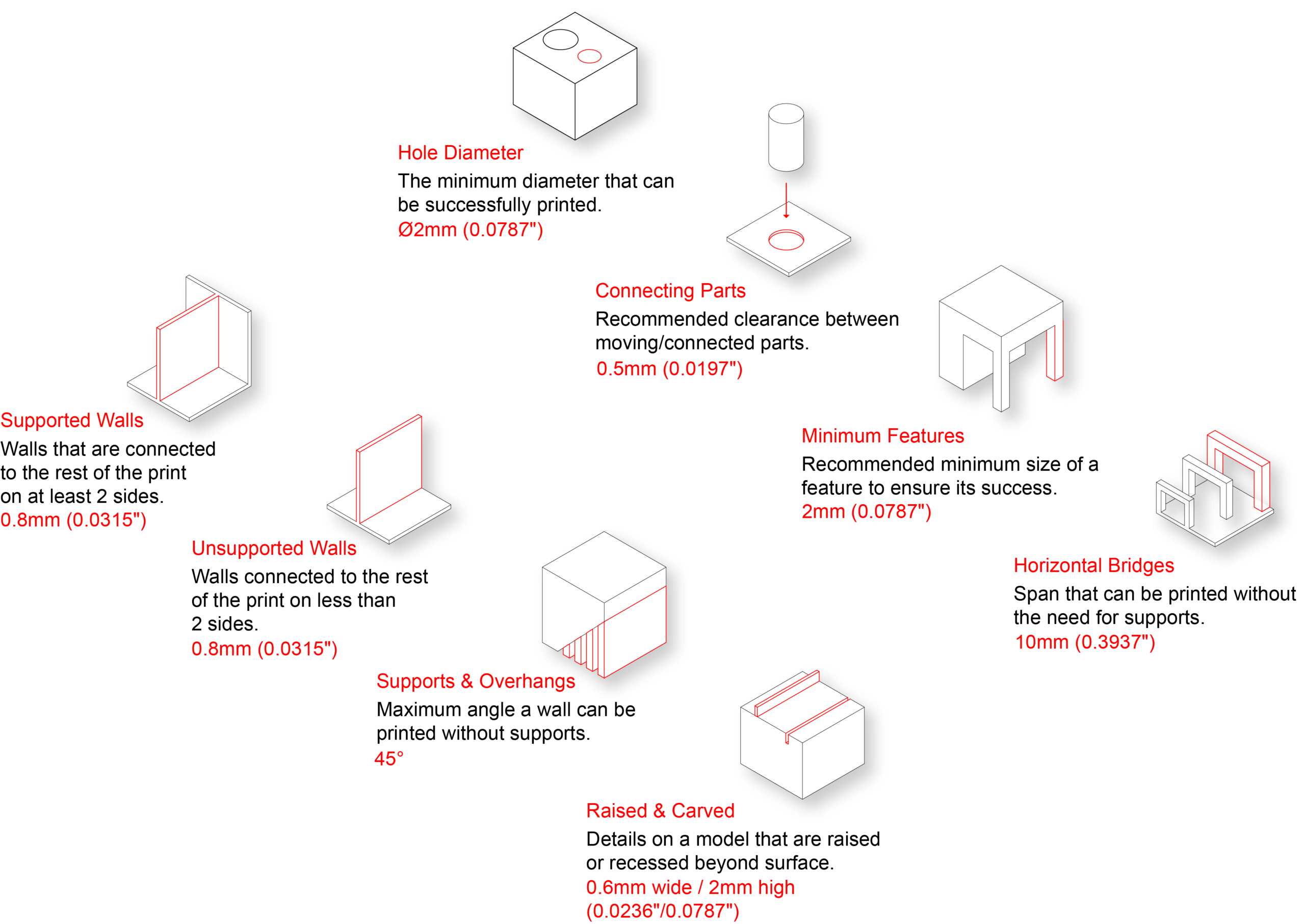
Naked Edges
Naked edges occur where surfaces or mesh faces fail to connect, leaving an opening in the model. For successful 3D printing, the model should form a closed, watertight volume.

Detecting Naked Edges:
- ShowEdges: Use ShowEdges and select Naked Edges to highlight openings in the model.
- ZoomNaked: Use ZoomNaked to locate and move between individual naked edges. This is especially helpful when troubleshooting complex models with small or difficult to find openings.
Repairing Naked Edges in Polysurfaces (NURBS):
- Unjoined Surfaces: If two surfaces meet correctly but remain separate, select them and use Join. If the edges are within the file tolerance, Rhino will join them.
- Planar Openings: Use Cap to quickly close planar openings in an otherwise complete polysurface.
- Missing Surfaces: Recreate the missing surface using the appropriate surface modeling tool, then Join it to the surrounding geometry. Common options include:
- PlanarSrf: Creates a flat surface from closed planar curves. Best for simple, flat openings.
- EdgeSrf: Creates a surface from two, three, or four adjoining edge curves. Useful for filling openings with clearly defined boundaries.
- Loft: Creates a surface through a series of cross-section curves. Useful when the missing surface transitions between multiple profiles.
- Sweep1 / Sweep2: Creates a surface using one or two rail curves and one or more cross-section curves. Useful for curved or more complex openings.
- Patch: Creates a surface fitted through surrounding curves, edges, or points. Useful for irregular openings where other surface commands are not practical.
- Misaligned Surface Edges: If adjacent surfaces do not meet, use ExtendSrf, Trim, or other surface editing tools to align their edges, then use Join.
- Complex Problems: Use Explode or UnjoinEdge to separate the affected surfaces. Repair or recreate the problematic geometry, then Join the surfaces back together.
Repairing Naked Edges in Meshes:
Mesh geometry requires different repair tools than NURBS surfaces and polysurfaces. If ShowEdges identifies naked edges on a mesh, use Rhino’s mesh repair tools to correct the opening.
- MeshRepair: Opens Rhino’s Mesh Repair tools to identify common mesh problems and access repair options.
- FillMeshHole: Fills an individual opening by creating new mesh faces across the naked edge boundary.
- FillMeshHoles: Automatically fills all openings in the selected mesh. This is useful for multiple small holes, but the repaired geometry should be reviewed afterward.
- MatchMeshEdge: Moves nearby naked mesh edges together so they meet. This is useful for small gaps where mesh faces should connect but are slightly misaligned.
- Fill: Creates new mesh faces from selected naked mesh edges and provides more control over how the opening is closed.
Tip: For minor mesh problems, MeshRepair or FillMeshHole will often be the simplest solution. If the mesh contains extensive errors or the repair significantly changes the intended geometry, return to the original NURBS model, correct the geometry, and export a new mesh whenever possible.
Verify the Repair:
After making repairs, run ShowEdges again to confirm that no naked edges remain. A finished NURBS model intended to represent a solid should be identified as a Closed Polysurface, while a printable mesh should form a completely closed mesh with no naked edges.
Warning: Avoid using JoinEdge simply to force NURBS edges together. JoinEdge can connect edges that fall outside the model tolerance, but it does not repair the underlying gap or inaccurate geometry. Whenever possible, correct the surfaces so they can be joined normally.
Non-Manifold Geometry
Non-manifold geometry occurs when surfaces or mesh faces connect in a way that does not form a clear, continuous solid volume. Unlike a naked edge, which represents an opening in the model, a non-manifold edge is typically shared by more than two surfaces or mesh faces.
Common Causes:
- Three or More Faces Sharing an Edge: Multiple surfaces or mesh faces meet along the same edge, creating an ambiguous connection.
- Internal Geometry: Extra surfaces or faces remain trapped inside an otherwise closed solid.
- Edge-to-Edge Connections: Two solid regions touch only along an edge rather than sharing a continuous volume.
- Point Connections: Separate volumes meet only at a single point.
- Intersecting Geometry: Separate objects overlap without being properly combined into a continuous solid.
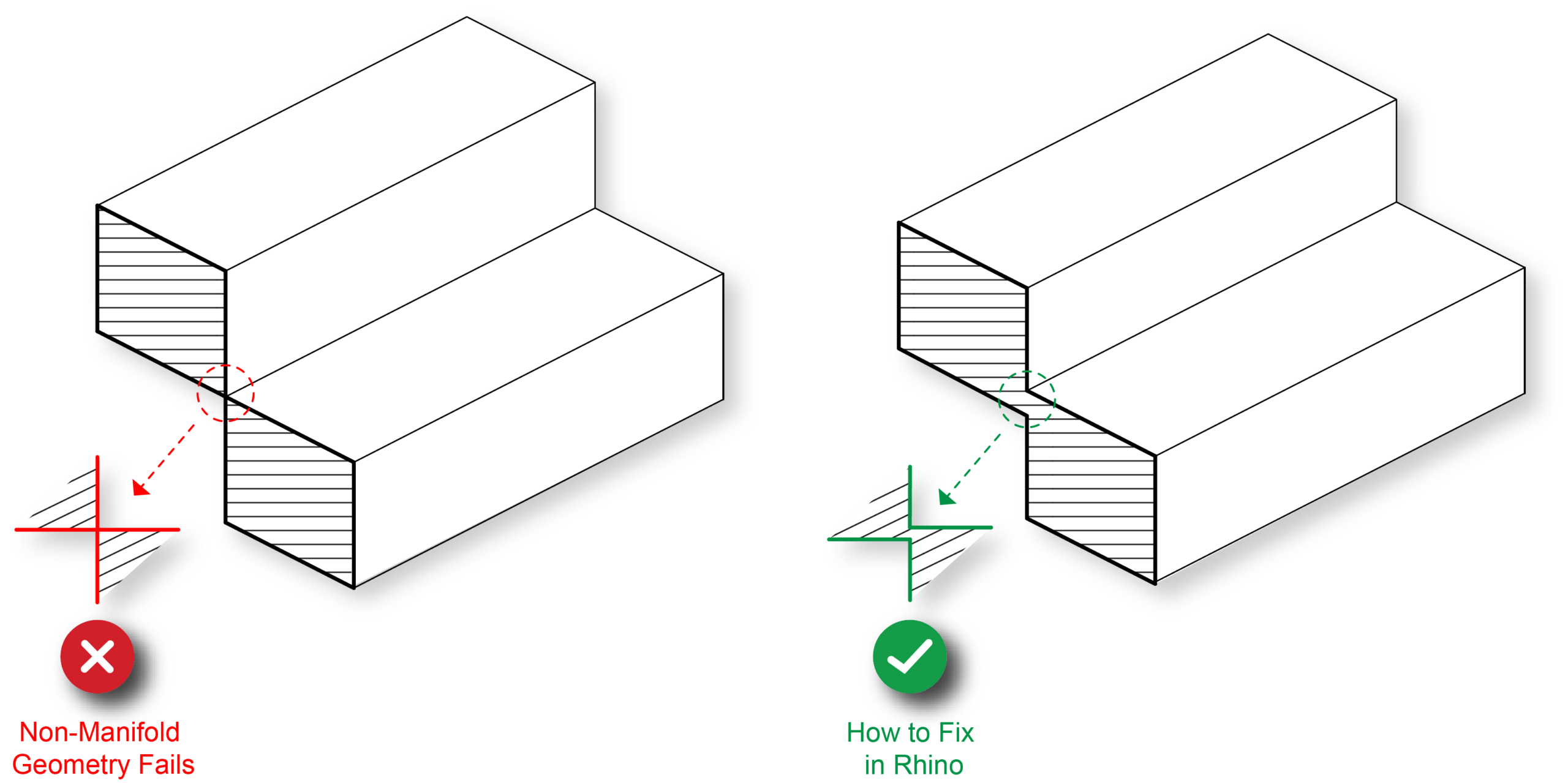
Detecting Non-Manifold Edges:
- ShowEdges: Use ShowEdges and select Non-Manifold Edges to highlight edges shared by more than two surfaces or mesh faces.
Repairing Non-Manifold Polysurfaces (NURBS):
- Internal Surfaces: Use Explode or UnjoinEdge as needed to access and remove surfaces trapped inside the solid, then Join the remaining surfaces.
- Intersecting Solids: Use BooleanUnion to properly combine overlapping closed solids that are intended to form one continuous object.
- Edge or Point Connections: Modify the geometry so the objects overlap with an actual volume, then use BooleanUnion to combine them.
- Complex Problems: Use Explode or UnjoinEdge to separate the affected surfaces. Repair or recreate the problematic geometry, then Join the surfaces back together.
Repairing Non-Manifold Meshes:
- MeshRepair: Use MeshRepair to identify non-manifold edges and access tools for repairing problematic mesh geometry.
- ExtractNonManifoldMeshEdges: Creates curves along non-manifold mesh edges, making problematic areas easier to locate and inspect.
- Internal Mesh Faces: Remove unnecessary faces trapped inside the mesh that do not form part of the exterior surface.
- Intersecting Meshes: Properly combine overlapping mesh objects using MeshBooleanUnion rather than leaving separate meshes intersecting.
- Complex Problems: Delete or rebuild the affected mesh faces so each edge is shared by no more than two faces.
Verify the Repair:
Run ShowEdges again and confirm that no Non-Manifold Edges remain. The finished model should form a clear, continuous solid volume before being exported for 3D printing.
Automatic Model Repair
Automatic repair tools can correct many common mesh errors after a model has been exported for 3D printing. These tools are useful for minor problems but should not replace properly constructed geometry in the original modeling software.
3DPrinterOS Automatic Repair:
After uploading an STL or OBJ, use the Repair tool to automatically analyze and repair common mesh errors, including:
- Holes and missing faces
- Non-manifold geometry
- Overlapping or intersecting faces
- Flipped or inconsistent face normals
After the repair is complete, carefully inspect the model and slice the repaired file to verify that the geometry has not changed unexpectedly.
Bambu Studio Automatic Repair:
The desktop version of Bambu Studio can also identify mesh errors and provides a Fix Model option for automatically repairing problematic geometry.
This can be particularly useful when 3DPrinterOS is unable to successfully repair a file. After running the repair, inspect the model carefully before exporting or uploading the repaired version to 3DPrinterOS.
Limitations of Automatic Repair:
Automatic repair software attempts to determine what the geometry was intended to be based on the existing mesh. When the model contains significant errors, the software may interpret that geometry incorrectly.
Automatic repairs can:
- Close openings that were intentionally part of the design.
- Remove or alter small features.
- Fill complex holes incorrectly.
- Change intersecting or overlapping geometry in unexpected ways.
- Produce a watertight model that no longer accurately represents the original design.
For this reason, always visually inspect the repaired model and review it in the slicer before printing.
Best Practice: Repair in the Original Modeling Software
Whenever possible, repair geometry in the original authoring software, such as Rhino, rather than relying on automatic mesh repair.
Correcting naked edges, non-manifold geometry, intersecting solids, missing surfaces, and other modeling errors in Rhino before exporting provides greater control over the repair and is less likely to unintentionally alter the design.
Recommended Workflow:
- Repair in Rhino: Correct geometry problems in the original model whenever possible.
- Export: Create a new STL or OBJ from the corrected geometry.
- 3DPrinterOS Repair: Use the automatic Repair tool for minor remaining mesh errors.
- Bambu Studio: If 3DPrinterOS cannot successfully repair the file, try Fix Model in the desktop version of Bambu Studio.
- Verify: Carefully inspect the repaired geometry and review the sliced layers before submitting the print.
Important: A successful automatic repair only means the software was able to create printable mesh geometry. It does not guarantee that the repaired model matches the original design intent.
