Why are my supports failing to generate even though they are enabled?
How do I fix geometry that is floating above the build plate?
Why are there no printers appearing in my 3DPrinterOS list?
Why are only a few printers appearing in my queue options?
What is the minimum wall thickness for 3D prints?
How do I scale my model to exact dimensions?
Why is my model significantly oversized or undersized when imported into 3DPrinterOS?
When should I submit my file to the 3D printing queue?
Section 1
Question: Why are my supports failing to generate even though they are enabled?
Answer: Supports typically fail to generate because of geometry errors, incorrect support settings, or excessive file complexity.
Explanation:
- Non-Watertight Geometry: Naked edges, non-manifold edges, open surfaces, and other mesh errors can prevent the slicer from correctly identifying the model’s exterior surfaces and unsupported areas.
- Small Gap Above the Build Plate: A model positioned slightly above the build plate may prevent supports from generating correctly beneath it. This commonly occurs when the model appears to be resting on the plate but is actually separated from it by a very small gap.
- Overhang Angle: Supports are generated only for surfaces that meet the selected overhang angle threshold. If the setting is too restrictive, the slicer may ignore areas that require support.
- File Complexity: Extremely dense meshes, large file sizes, or models containing many separate objects can slow the slicing process or cause support generation to fail.
How to Fix:
- Repair the Geometry in Rhino: Use the ShowEdges command to identify naked or non-manifold edges. Repair any openings or geometry errors and confirm that the model is a closed solid before exporting.
- Check the Build Plate Position: Use the Set to Build Plate tool to ensure the model is resting directly on the build plate. If the model has a curved or angled base, raise it enough for the slicer to clearly recognize the gap.
- Review the Support Settings: Check the Overhang Angle and other support settings in the slicer. Adjust the angle so the intended surfaces qualify for support generation.
- Reduce File Complexity: Simplify overly dense meshes or separate complex models into multiple files before slicing.
- Verify the Sliced Preview: Review the model layer by layer in the Cloud Slicer and confirm that supports appear beneath all required areas before submitting the print.
Section 2
Question: How do I fix geometry that is floating above the build plate?
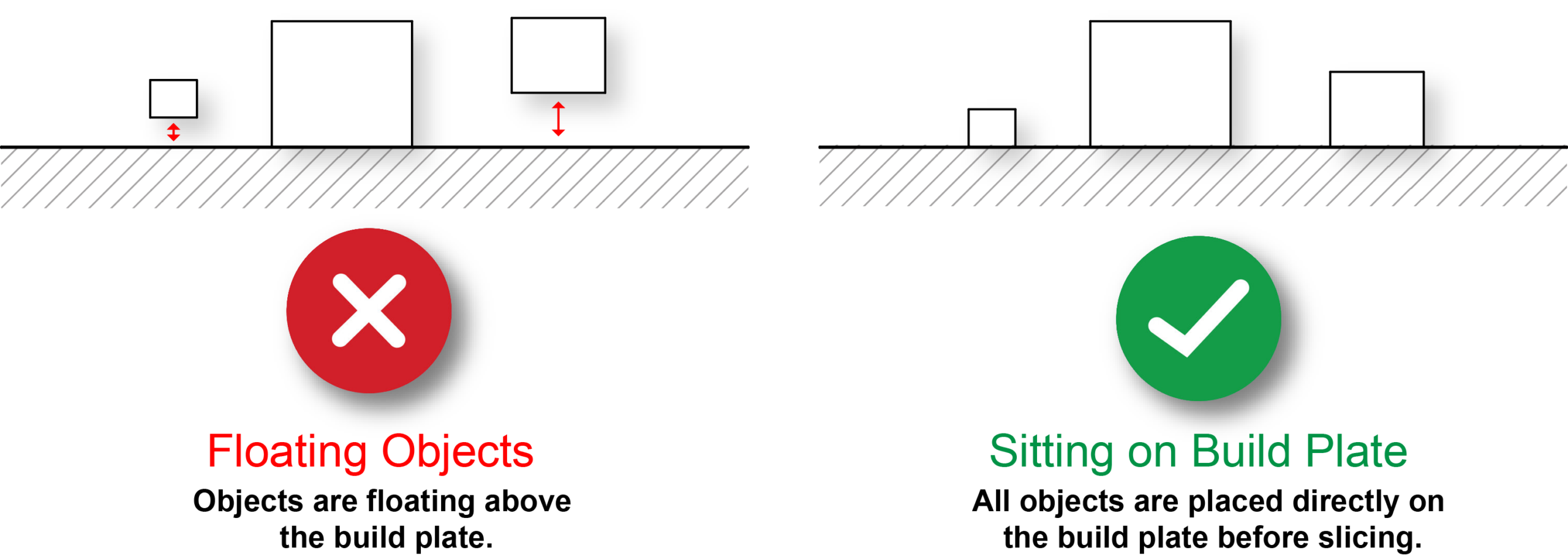
Answer: Use the “Set to Build Plate” tool in 3DPrinterOS to place your model on the build plate before slicing.
Explanation: A 3D printer builds each layer from the build plate upward. Any portion of the model that begins above the build plate without support underneath cannot be printed and will typically result in a failed print or “spaghetti” failure.
Common Causes:
- Model Positioned Above the Build Plate: If the entire model is floating above the build plate, use the Set to Build Plate tool in 3DPrinterOS to move the lowest point of the model to the build plate.
- Multiple Objects at Different Heights: If your STL contains multiple objects positioned at different elevations, the Set to Build Plate tool will align only the lowest object with the build plate. The remaining objects may still be suspended above the build plate and will not print correctly.
- Non-Planar Bases: Models with curved, angled, or uneven bottom surfaces have limited contact with the build plate, which can reduce bed adhesion and cause portions of the model to begin printing in mid-air.
How to Fix:
- Align the Model in CAD: Before exporting, position the base of the model at Z = 0 in Rhino. If exporting multiple objects in one STL, ensure they all rest on the same horizontal plane.
- Use Supports When Needed: If your design includes overhangs or an intentionally curved or angled base, enable supports in the slicer. Raising the model approximately 1/8 in. (3 mm) above the build plate often allows supports to generate more effectively beneath the model.
- Verify the First Layer: Before sending the print to the queue, inspect the first layer in the Cloud Slicer. Confirm that every part of the model intended to contact the build plate has a solid footprint or is properly supported.
Section 3
Question: Why are there no printers appearing in my 3DPrinterOS list?
Answer: Your 3DPrinterOS account is likely not connected to the UNLV School of Architecture workgroup.
How to Fix:
- Use the Correct Login Method: Log in to 3DPrinterOS using UNLV’s Single Sign-On (SSO).
- Request Workgroup Access: If no printers appear after signing in through SSO, contact Kyle Kithas to obtain the School of Architecture workgroup access code or have your account added manually.
Section 4
Question: Why are only a few printers appearing in my queue options?
Answer: You can only queue a file to the specific printer model for which it was sliced.
Explanation:
- Machine Specific G-code: Slicing converts your 3D model into machine instructions called G-code. These instructions are generated for a specific printer model and include settings such as build volume, nozzle size, movement limits, and temperature requirements.
- Compatibility Filtering: 3DPrinterOS only displays printers that are compatible with the selected slicing profile. For example, if a file is sliced for a Bambu Lab P1S, printers with different profiles, such as the X1 Carbon or H2S, will not appear as queue options.
How to Fix:
- Verify Slicer Settings: Before slicing, confirm that the printer selected in the Slice Tool matches the printer model you intend to use.
- Re-slice for a Different Printer Model: To use another printer type, return to the Slice Tool and slice the model again using that printer’s profile. The compatible machines will then appear in the queue options.
- Check Queue Times: To minimize your turnaround time, look at the lab’s active queues and slice your model for the printer type with the shortest wait.
Section 5
Question: What is the minimum wall thickness for 3D prints?
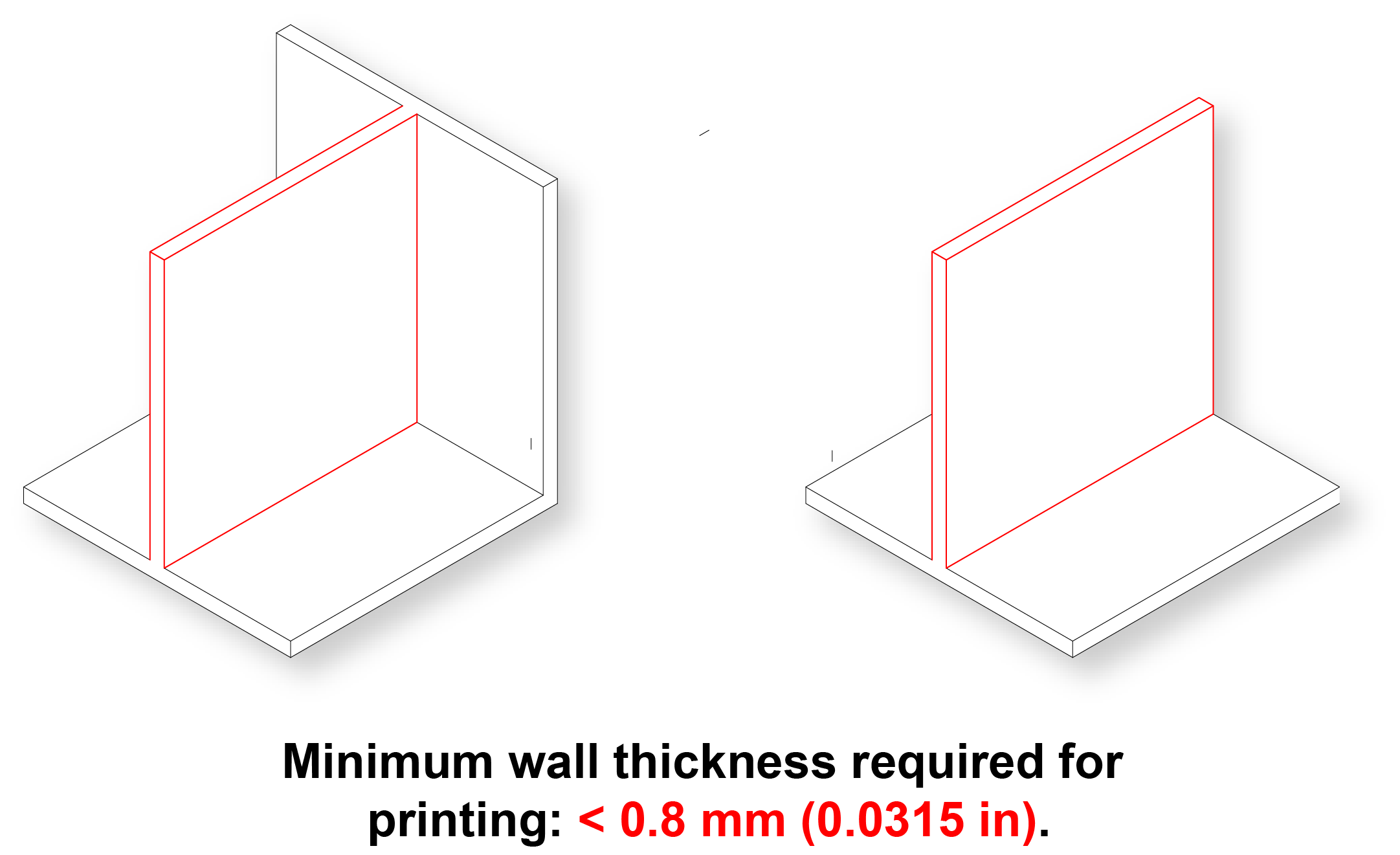
Answer: Walls must be at least 0.8mm thick.
Explanation:
- The Rule of Two: Our printers use 0.4mm nozzles. A 0.8mm wall allows for two full passes of the extruder, which is essential for structural integrity.
- Avoid Fragility: A 0.4 mm wall may print as only a single extrusion path. These walls are extremely thin and can break easily, deform during printing, or fail to print consistently.
- Improve Layer Bonding: A 0.8mm wall provides enough surface area for the plastic to fuse properly, ensuring your model stays in one piece.
How to prep:
- Check Your Units: Confirm that your Rhino file is set to millimeters so wall thicknesses can be measured accurately.
- Verify the Thinnest Areas: Use the Distance command in Rhino to measure the narrowest walls in your model. Make sure all walls are at least 0.8 mm thick before exporting the file to 3DPrinterOS.
Section 6
Question: How do I scale my model for 3D printing?
Answer: Use the ‘Scale’ command to resize your model while maintaining its proportions.
Methods for Precise Scaling:
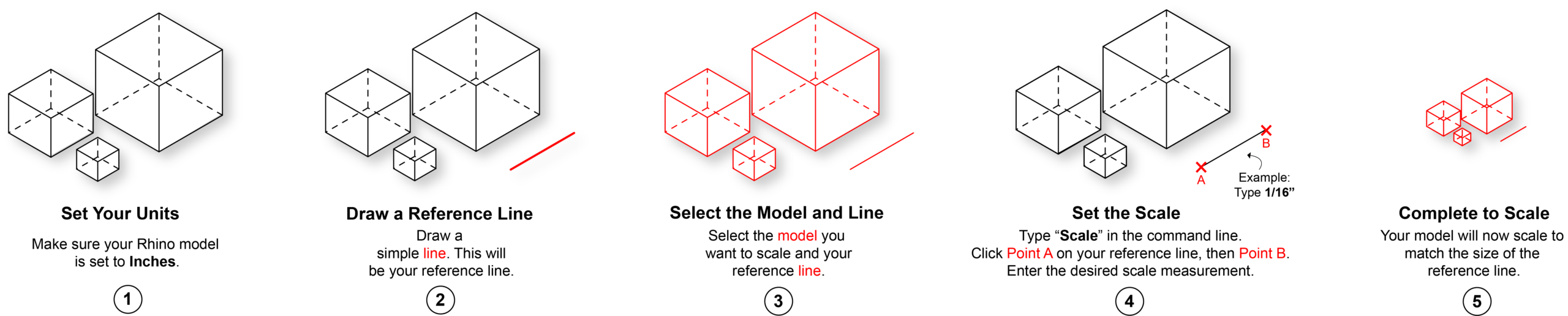
- Reference Line Method: This method is useful when your Rhino model is drawn at full scale (1:1) and you need to resize it to a specific architectural or engineering scale.
- Draw a line representing the second value of your desired scale:
- For 1/16″ = 1′-0″, draw a line 1′-0″ (12 inches) long.
- For 1:500, draw a line 500 feet (or 500 meters, depending on your project units) long.
- Select both your model and the reference line.
- Type ‘Scale’.
- For the Base Point, select one end of the reference line.
- For the Reference Point, select the opposite end of the reference line. Rhino uses the distance between these two points as the current reference length.
- When prompted for the new length, enter the first value of your desired scale:
- For 1/16″ = 1′-0″, type 1/16″.
- For 1:500, type 1ft (1 m, depending on your drawing units).
- Draw a line representing the second value of your desired scale:
- Scale by Reference (Absolute): This method is useful when a specific feature of the model must have an exact final dimension.
- Select your model.
- Type ‘Scale’.
- Select a Base Point at one end of a known dimension.
- Select a Second Reference Point at the opposite end of that dimension.
- Enter the desired final length, such as 150mm, and press Enter.
Pro Tip: Always verify your units (‘Units’ command) before scaling.
Section 7
Question: Why is my model significantly oversized or undersized when imported into 3DPrinterOS?
Answer: This is caused by a unit mismatch between your CAD software (Rhino) and the 3DPrinterOS slicer. STL files do not store unit information, so 3DPrinterOS interprets the model’s numerical dimensions as millimeters. For example, a model that is 1 inch or 1 foot long in Rhino may be imported as only 1 millimeter long.
Explanation: Most 3D printing software, including 3DPrinterOS, assumes that STL files units are millimeters (mm). If your Rhino units are set to inches, feet, or meters, the model will be imported at the wrong scale.
- Oversized Models: These often exceed the printer’s build volume, making them impossible to slice or print.
- Undersized Models: These can become so small that the printer cannot resolve the details (tolerance issues), resulting in “spaghetti” failures or extremely fragile prints.

How to Fix:
- Standardize Units: After scaling the model in Rhino to a specific architectural or engineering scale, use the Units command to convert your file to millimeters before exporting your STL. Ensure you select “Yes” when asked to scale the geometry.
- Cloud Conversion: If you have already uploaded a file in inches, use the “Inches to MM” conversion tool within 3DPrinterOS to correct the scale.
Section 8
Question: When should I submit my file to the 3D printing queue?
Answer: Submit your file at least 10 days before your project deadline.
Why submit early?
- High Demand: During peak periods, the print queue can exceed one week as students work toward major project and review deadlines.
- Print Failures: 3D prints are not guaranteed to succeed on the first attempt. Submitting early allows time to troubleshoot, revise, and reprint if needed.
- Long Print Times: Individual models may take 12 hours or more to print, which can significantly increase queue times.
Guidance: Finalize your geometry and submit your job at least 10 days in advance. This provides time to address potential file or printing issues and improves the likelihood that your model will be completed before your deadline.
